Technical Description:
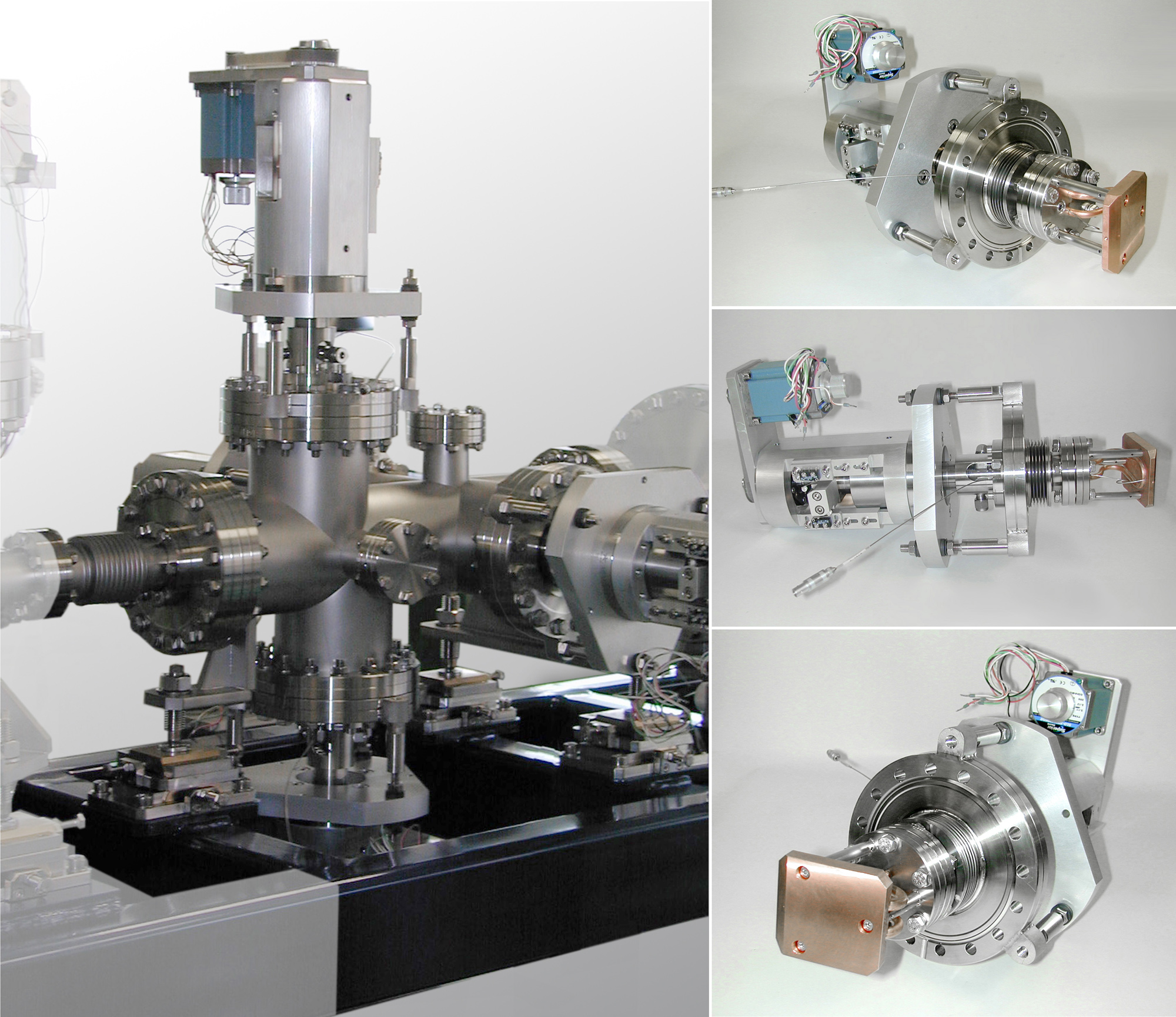
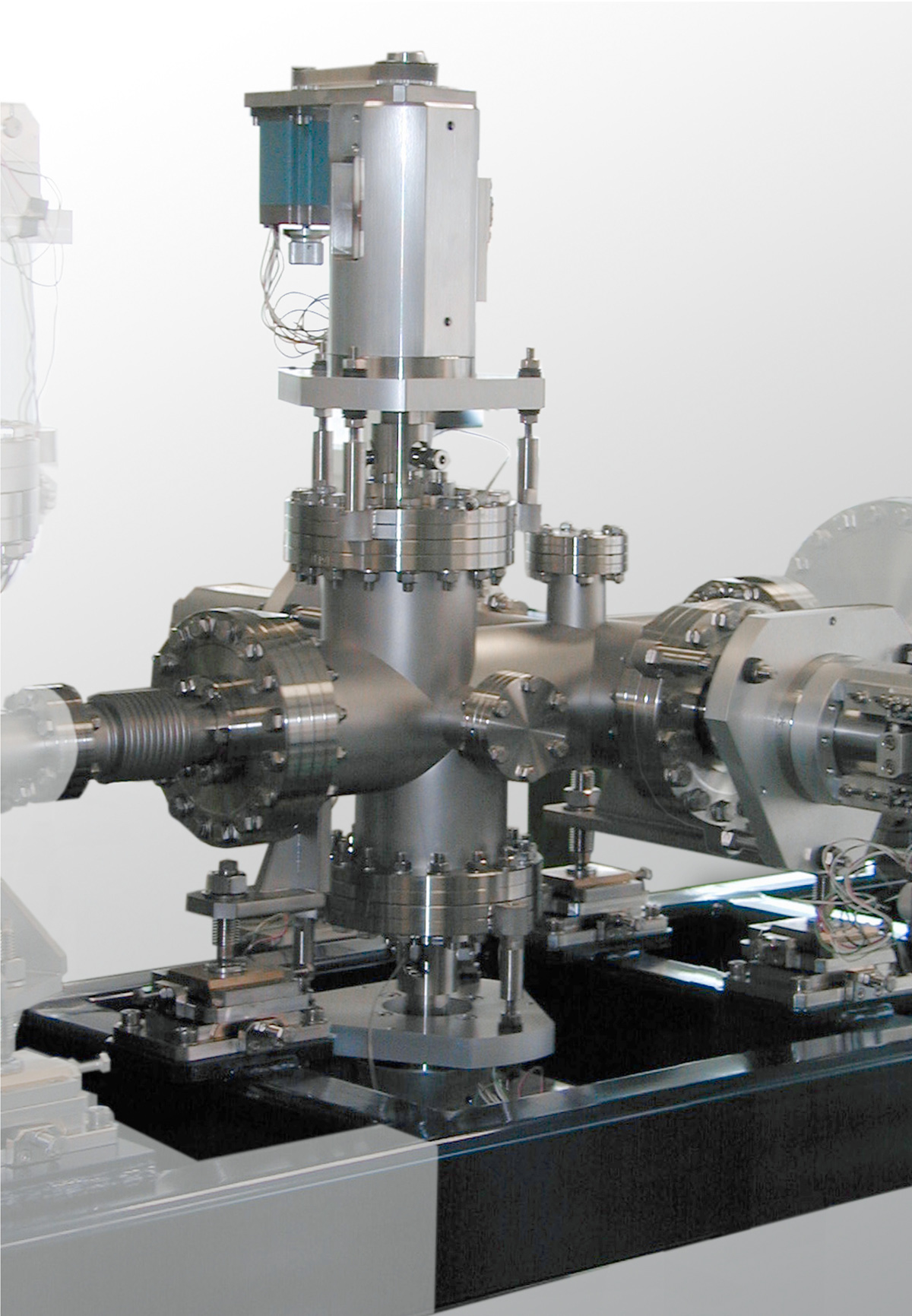
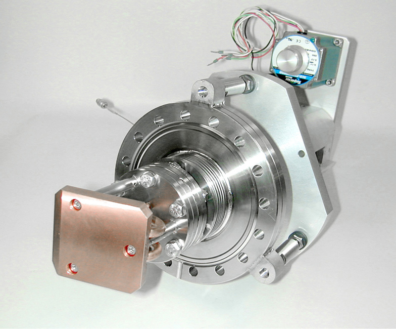
Each system consists of two or four slit heads and manipulators.
The slit system is based on a uniform and modular concept with
- stroke unit optionally driven by stepping motor with or without synchronous belt gear
- cooled or uncooledslit jaws made of OFHC-Copper, Glidcop® or Tungsten
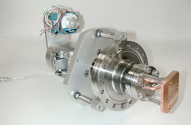
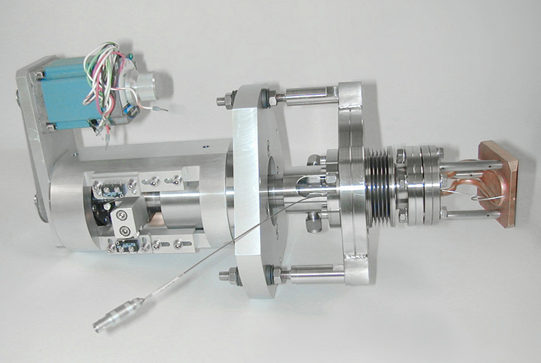
The linear drive system is mounted on a base flange CF100. The system can be equipped with end switches, reference points or linear encoders. The linear feedthrough to the vacuum is realised by a welded bellow. The vacuum side interface for the elements to be moved is a flange CF54.
Depending on the heat load and the slit precision various slit heads can be connected to that interface flange on the vacuum side. A standard slit head consists of e.g. an inclined copper or Glidcop® plate with water cooling on the backside. In case of a high thermal load a tungsten cutting edge is inserted into the copper plate. For temperature control of the slit head a thermocouple can be fitted as an option.
Technical Data:
| Dimensions of manipulator slit system: - Width (with synchronous belt drive) - Height |
228 mm 310 mm outside basic flange |
|
| Base flange: | DN 100 CF | |
| Interface flange: | DN 54 CF | |
| Stroke: | ± 12.5 mm | |
| Resolution: | 0.001 mm | |
| Repeatability: | 0.002 mm | |
| Repeat accuracy of reference point switch: | ± 0,002 mm | |
| Leakage rate: | < 1 x 10⁻¹⁰ mbar l s-1 |


