")
")
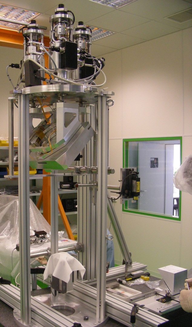


IR Beamline B22
Technical Description:
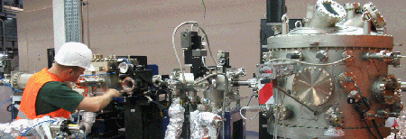
Beamline B22 will be a InfraRed MicroSpectroscopy facility to perform diffraction limited microscopy and molecular sensitive imaging on both biological systems and inorganic materials.
Fourier Transform IR interferometers coupled to IR microscopes on two experimental end stations will span the whole IR range from the near to the far–IR.
Technical Data:
| Radiation | IR photon beam, maintaining synchrotron radiation brightness in the whole spectral range from 10000 cm-1 (λ=1 λm) to 20 cm-1 (λ=500 λm). Bending and edge radiation IR sources. |
|
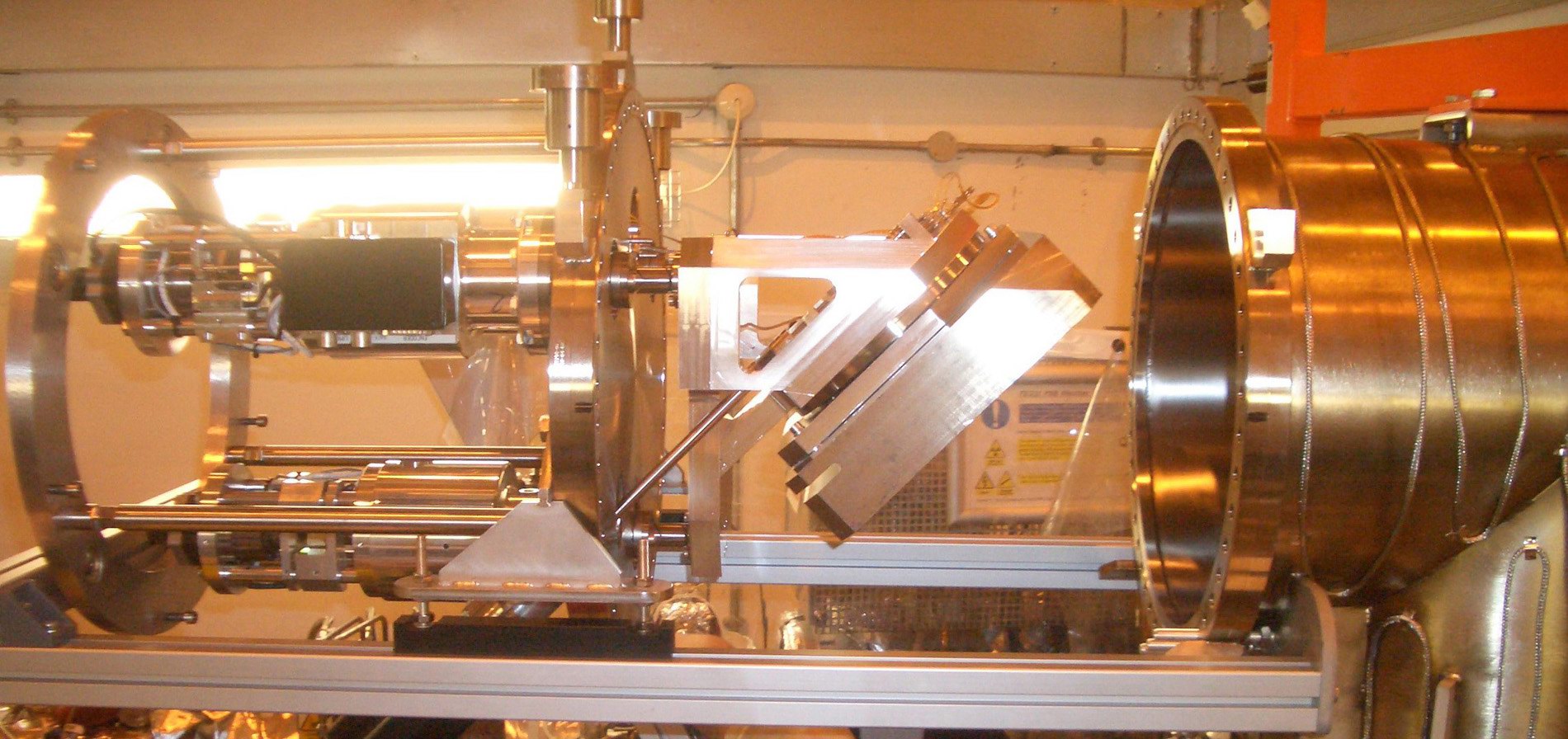
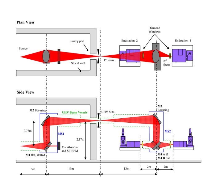
| Overview | Visible to far-IR components of the SR will be mirror reflected with high efficiency on metallic surfaces, and refocused twice by ellipsoidal mirrors to go through, respectively, the survey port and the final IR transparent windows. Mirrors M1 and M2 are sited in the front end area within the Diamond storage ring to, respectively, deflect upward and focus the SR beam through the storage ring shield wall aperture(survey port). Mirrors M3, M4a plus M4b are located in cabins outside the storage ring to deflect downward and refocus the beam to the line ends (diamond windows). |
|
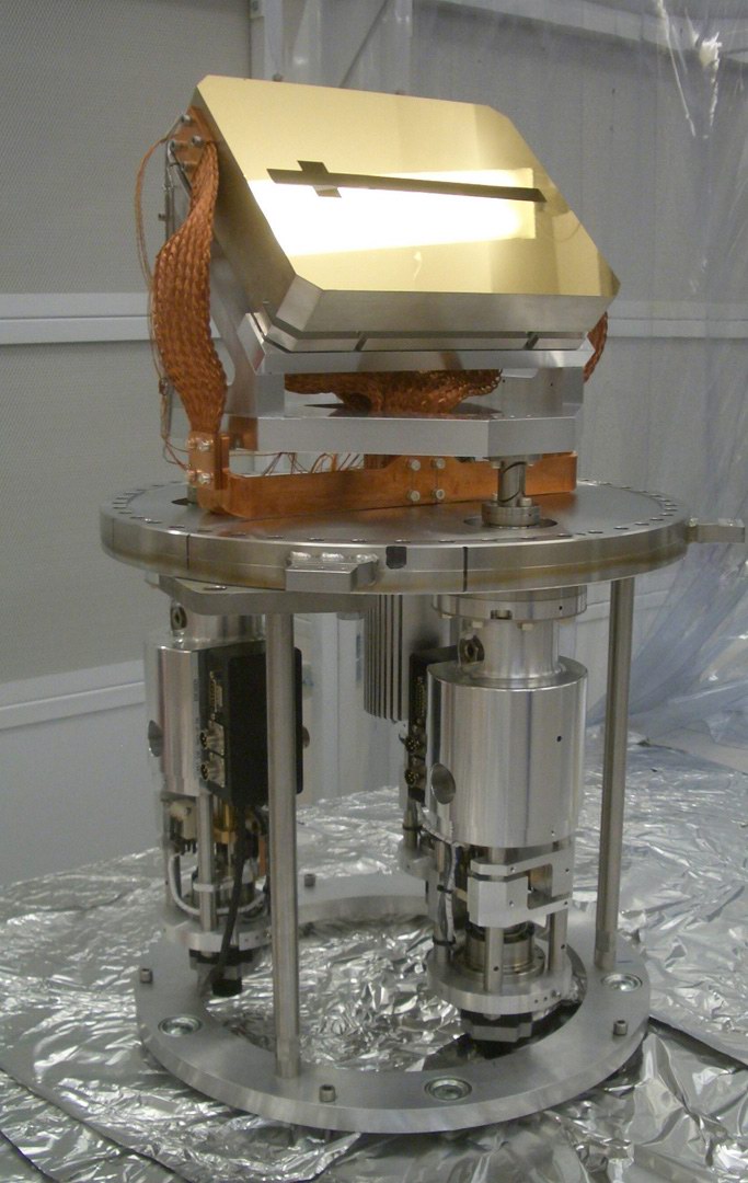
| Optics | The first optical element in the beamline is a plane, gold coated, aluminium alloy mirror, M1. This is placed 5.00 m from the bending magnet source and at 45° with respect to the incident beam that deflects vertically the IR and visible SR to a second mirror M2. M1 is un-cooled to prevent any vibration issues, so excessive heat-load is avoided by a horizontal slot in the centre to reject the X-ray component confined in the central part of the synchrotron beam (~ 2 mrad vertically centred on the SR emission plane). The second optical element of the front-end is an ellipsoidal gold coated mirror M2 at an angle of 45° with respect to the vertical beam leaving M1, that focuses the SR light through the survey port in the shield wall. M2 will be located 0.77 m above M1 and at 2.17 m elevation from the floor (for a final distance from the 1st focal spot of 13.00 m). The third optical element, outside the shield wall, is an ellipsoidal gold coated mirror M3 at an angle of 45° with respect to the beam leaving M2, that focuses SR light downward. The mirror will be located 26.00 m downstream of M2, and is to be at the same height. M3 refocuses the image from the 1st focus (13.00 m upstream of M3) to the end of the beamline (2.77 m downstream of M3 and 80 mm after the diamond windows), via mirrors M4. The final optical elements are the two plane, gold coated, aluminium mirrors M4a and M4b. M4a will be at 45° with respect to the vertical beam from M3 and will pass the beam towards one diamond window. M4b will be at -45° with respect to the vertical beam leaving M3 and will pass the beam towards the opposite diamond window. M4a and M4b will be located 1.15 m below M3 (1.02 m above floor level), they will be fixed at 90° one to the other and each large enough to take the entire IR fan. The pair of mirrors are to be moved in and out of the beam leaving M3 to select which fraction of the IR fan is be passed to each end station. Beam Options will be: all radiation to end station 1, all radiation to end-station 2 or a fraction of the SR (edge and bending fans) to each end station simultaneously. |
Customer & Period:
| Customer: |
Diamond Light Source | |
| Period of Implementation: |
July 2008 to July 2009 |
JUX_PORTFOLIO_PRO_DATE
September 7, 2022
JUX_PORTFOLIO_PRO_CATEGORY
ROOT
JUX_PORTFOLIO_PRO_TAGS