")
")
Technical Description:
For the DLS contract a total of 10 aluminium vessels have been manufactured with bimetal CF flanges:
- 8 pieces of a length of 947mm and
- 2 pieces of a length of 4900mm.
- These vessels have been delivered with exactly fitting bakeout jackets from the company Horst.
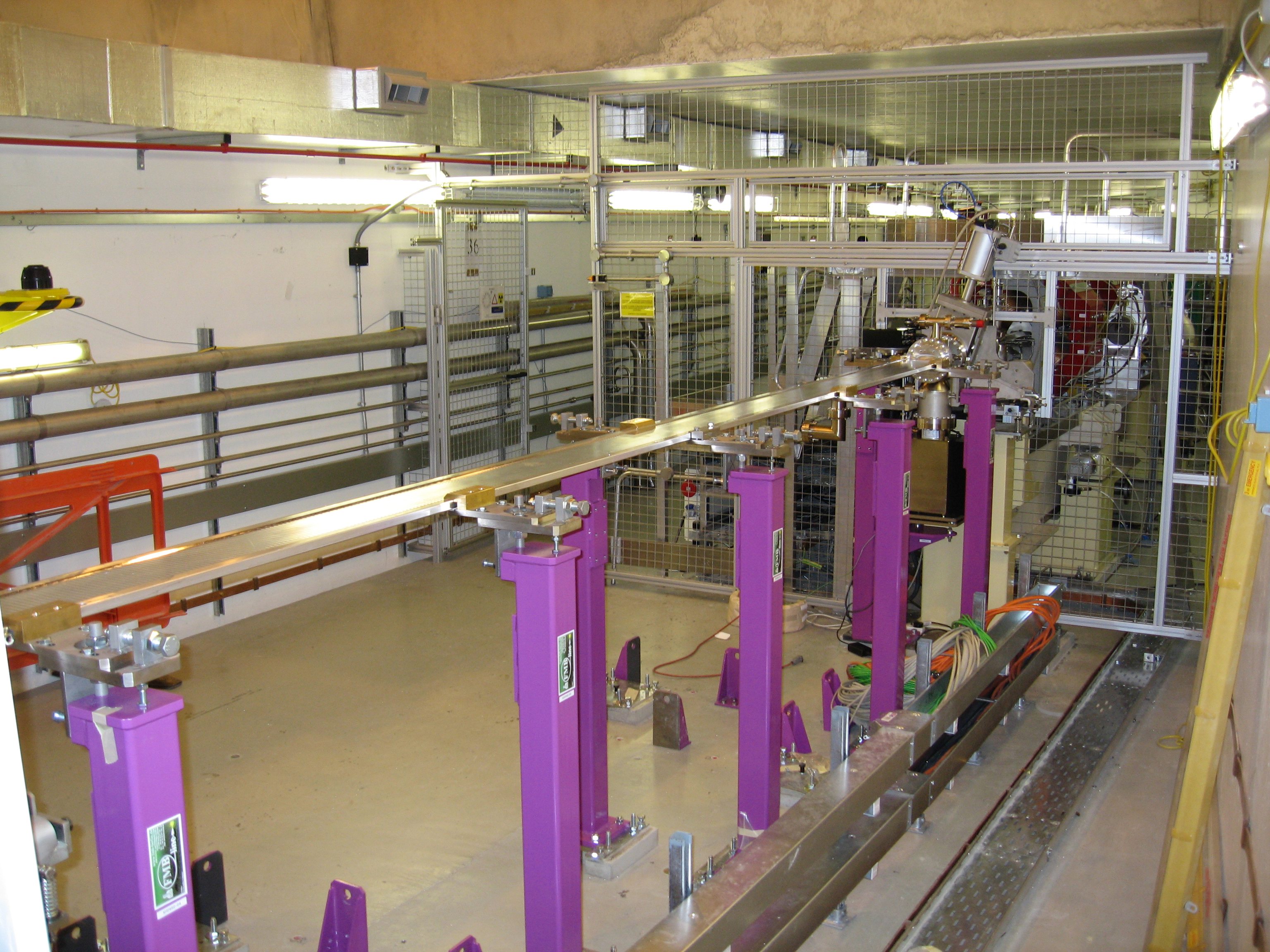
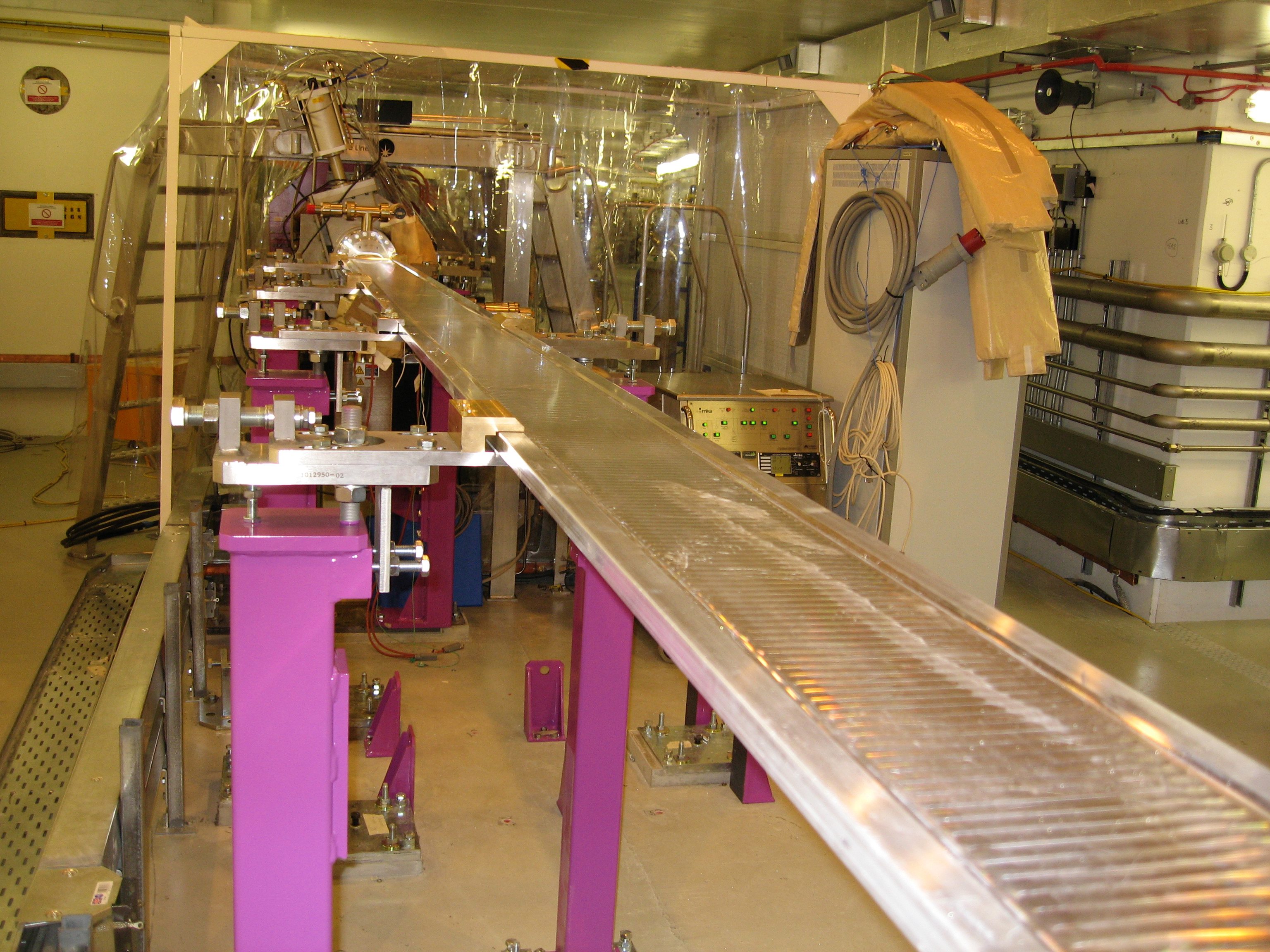
- In the storage ring these vessels rest on stands. On the top these stands are fitted with an adjustable clamping device where the Al vessel is clamped and held on both outer sides
Each vessel includes:
- 1 profile section,
- 2 CF bimetal flanges,
- 4 stiffeners,
- 4 sealing plugs,
- 4 Swagelok threaded fittings,
- 1 exactly fitting strong back and
- one interior NEG coating.
The actual vessel profile section is an extruded aluminium section with the outer dimensions of 208mm x 20mm.
In the centre there is an elliptical channel of 74mm x 11mm. On the left and right from this ellipse there is a through hole on each side with a diameter of 6mm. These through holes are used for water–cooling the vessel section after installation in the storage ring.
At the section ends these channels are closed using plugs. The required cooling water is passed into the longitudinal channels via 2 additional bore holes each (made from the narrow outer side of the profile section.
The connecting joints are threaded fittings made by SWAGELOK. A flexible Al gasket is used as a sealing.
Bimetal blind flanges made by the company ATLAS are used as connecting flanges.
The flange face of these flanges consists of high–quality stainless steel (316L) and the rear side of an Al alloy (6061–T6) which can be welded well.
Both flange halves are connected via explosion bonding.
Titanium and copper are used as bonding materials between stainless steel and copper.
These bonding materials are used as thin sheets.
Flanges and vessel profile section are welded using HF and TIG welding techniques.
Stiffeners are tack welded between the outer diameter of the flange and the vessel profile section in order to additionally increase stability of the welds.
Additionally it is recommended to perform each transport after mechanical completion by using a strong back which is "made to measure".
This strong back consists of:
- two transit blocks each (The transit blocks are two solid Al plates, which are fixed above and below the vessel via form fitting at the two ends of the Al vessel and whose front sides are at the same time mounted against the rear sides of the bimetal flanges. This ensures the perpendicularity of the bimetal flanges towards the vessel axis in both directions at right angles towards the beam axis and prevents an overstressing of the Al weld.) and
- a connecting section. Depending on the length of the Al vessel additional folding holders are welded on to this section, which prevent the whole vessel from deforming.
- Transit blocks and connecting section form a unity and are screwed with one another.
Interior coating of the Al vessel – NEG (non– evaporable getters) coating (approx. 1µm)
- Getters are materials capable of adsorbing gas molecules by chemical forces.
- Before NEG– inside coating of the vacuum vessel: It must be cleaned according to a special technology of CERN, to dissolve the native oxide layer completely.
- At room temperature NEGs are able to pump most of the gas with exception of rare gases and methane and other light hydrocarbons.
NEG thin films have several advantages comparable to a well–known NEG–strip and pumps:
- They trap the gas coming from the substrate materials.
- After activation a NEG film is a clean metal surface resulting in a large pumping speed and reducing degassing (both thermal and ion/photon/electron induced).
- These NEG– films do not need space, electrical feedthroughs or insulation.
Technical Data:
| vessel length: | 4900mm (2x) and 947mm (8x) – for DLS | |
| Layer thickness: | approx. 1 µm (variations ±20%) The interior elliptical profile section (74mm x 11mm) has been coated using 3 electrodes simultaneously. The variations in layer thickness result from the respective distances to the electrodes. The resulting layer thickness was substantiated on a test coupon. |
|
| Coating company: | SAES Getters in Lainate / Italy | |
| Number of possible activations of the layer: | approx. 20 times |
Customer & Period:
| Customer: |
Diamond Light Source DLS | |
| Period of Implementation: |
February 2006 to June 2006 |